I have been an Electronic Technician my whole adult life
My last job was a Purchasing Agent for a small Electronic Equipment Manufacturer
I also set up and ran their one man Surface Mount Technology department
I bought tiny electronic components for 41 different circuits in a dozen products
I ordered custom made circuit boards and custom parts made of metal, plastic and glass
If you want to jump ahead to the videos, click on videos
Take a look at the 5 components sitting on the tip of my finger.
As you can see, I either have an enormous finger or these parts are really tiny.
Your cell phone probably has hundreds of these tiny parts, to make the phone work.

Here are some chips compared to a penny. The chip is the same size as the I in liberty!

And this is how these parts come from the factory. The sprocket holes are used to advance the strip to the next available part. The thick white paper strip is called the carrier tape and it has a cover strip of thin plastic that is lightly stuck onto the paper to hold the parts in place. After the Juki picks up each part, the feeder advances the carrier tape to the next part as it pulls back the cover tape to expose the part.

Here I am in Las Vegas at the Apex Expo convention that caters to electronic manufacturing equipment
Apex Expo is a fascinating place with amazing machines from several brands that pick up tiny parts and place them onto circuit boards at record speeds and accuracies.
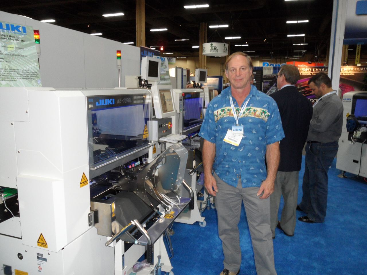
I was sent to decide which pick and place machine would be the best fit for the mom and pop I worked for. The Juki brand was low cost compared to some large machines with seven digit price tags! Juki America is located in Fremont, CA and they have free training classes to learn how to properly operate, maintain, calibrate and repair the Juki as needed. I enjoyed the two drives to Fremont for the operation and then the maintenance classes.
This is the one I picked out, a Juki-KE-2080L. With a full compliment of feeders, and three trolleys, it was several hundred thousand dollars!
The software is German and the machine is made in Japan. The instructions and error messages can be very entertaining to say the least!

This KE-2080L measures 5 feet by 6 feet by 9 feet and weighs a ton and a half, literally just over 3000 pounds!
It has 6 heads that move up and down to pick up the parts, and it uses multiple lasers to measure each part. This Juki can pick up 6 components simultaneously, measure the height, width and length of all 6 components, verify that all 6 parts match the stored data for those parts, and then one at a time, place all 6 components on the PCB exactly where specified.
Amazingly, it only takes about a second to pick and place 6 parts,
and the placement accuracy is extremely accurate at 1 micron, 1 millionth of a meter!
This is what the inside of the Juki looks like with the safety cover open. The gantry assembly is in the top center of the picture. The gantry can move to the front row or to the back row to pick up parts, and large parts can be picked up from trays located in the center of the machine
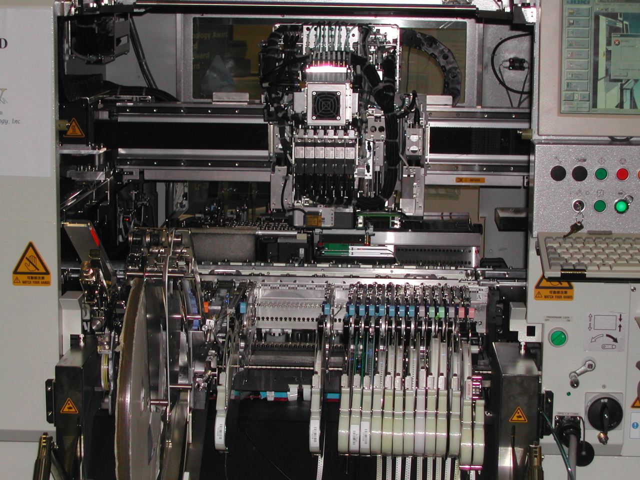
The large black stripe behind the gantry is a toothed belt that drives the gantry right and left.
There are also two toothed belt assemblies that move in unison on both sides of the Juki to drive the entire gantry assembly front to back. The gantry can move from one corner to the other in a second at top speed!
This is the view of the back side of the Juki at rest. The bottom of the gantry is at the top center of the picture.

To the left of the gantry is the Integrated Circuit chip tray. Chip trays with from 18 large parts to 240 small parts come from the manufacturer on a tray. The Juki software only needs the position of the first chip, the spacing between the chips and how many rows and columns there are on the tray. Once you have defined the tray, the Juki will know where to pick up each chip, and it will remember which slots are empty.
On the other side of the galley is the nozzle holders. The smallest parts need a tiny nozzle to pick them up with vacuum. Larger parts and heavier parts need bigger nozzles. Once all the smallest parts have been placed, the gantry will go to the nozzle area for a "pit stop", so that it can deposit its six number 1 nozzles back in their holders and pick up six number 4 nozzles for the bigger parts. The heads and nozzle holders are lined up so that the Juki can remove or add 6 nozzles simultaneously. There are several sizes of nozzles available and special nozzles for parts with a rounded top like an LED
The Juki can accommodate 40 small parts in the front galley and another 40 in the back side galley.
And if that isn't enough parts, the parts can be installed on removable trolleys, and whole trolleys of parts can be swapped out for any other trolley of parts in a few seconds. The bottom of the picture shows what a full trolley of 40 small reel parts looks like. Most of these reels hold 5000 parts. Amazingly, reels of these common parts are often only $5 to $10 per reel of 5000.
The Juki can also handle large complex chips, like this one with 25 pins on each side of a body that can easily fit on top of a quarter. Chips come in dozens of standard packages.

This package is called a TQFP-100, Thin Quad Flat Pack with 100 pins.
For these chips, the Juki has a special 7th head that picks up a chip from a tray and holds it over a camera to take a picture of it. If the picture it takes, like this one that the Juki took, matches the picture it has in memory for it, then the Juki will place the chip on the PCB where it belongs. All 100 pins have to be present and inside the boxes. It checks to make sure there is a space between every pin and that none of the pins are bent. Since this part will sit down on its 100 leads, the Juki needs to make sure that the bottom of every lead are on the same plane so that all 100 pins will touch the board properly to get soldered properly. If even one pin is out of place, the Juki puts the chip in a reject bin to be dealt with later and then it tries the next chip on the tray.
This is a really cool high tech package, called a UBGA-342 which stands for Micro Ball Grid Array with 342 pins.
This part's package is square and will fit on a dime and is as thin as a dime!

This is the actual picture that the Juki took of one of these chips. Like the previous chip, it will use this picture to compare to the picture of the part that it picked up.
It has 342 contacts underneath the chip that are in this pattern. The circuit board will have this exact pattern of dots on it and each dot will have a tiny mound of solder paste on it. The Juki places the chip on the board, and all 342 pins sit on the mound of solder paste intended for each pin. When the PCB runs through a reflow oven, the oven will melt all 342 solder mounds and the chip will be perfectly soldered into place when the board comes out of the oven.
This chip is almost perfectly symmetrical, so how will the Juki know if it is facing the right direction? There is one pin that makes one side different, and the Juki will spot that difference and use it as its reference so it knows that the chip is facing the right way, can you spot the different side?
Large reels of medium sized parts are very common.
There are square, flat, cylindrical, rectangular, oval and other odd shaped parts of many sizes.

These type of parts are usually supplied on a plastic carrier tape that has a recess for each part. The reels have sprockets at the edge so that the machine can advance each reel after a part is picked up. The parts are kept in place by a strip of thin plastic stuck on to the top of the reel. After each part is picked up, the feeder that held the picked up part advances to the next part while also peeling back the cover strip to expose the next part so that a nozzle can come down and contact it, and then pick it up with vacuum.
Here are some short video clips to see the Juki in action.
The first video shows a circuit board being brought into the Juki by it's conveyor belt.
The Juki looks at 3 fiducial's, seen as the three flashes of orange light, to make sure the right board was fed in and it is facing the right way. Since the fiducial's were present in the right places and they matched the standard picture of the fiducial, the Juki started to place the components. 24 parts were placed in this clip. When the gantry comes to the front to pick up parts, it almost always picks up 6 at a time.

Incoming video
This close up still shows one nozzle, the green part and below, making contact with a part in a feeder.
The video shows all 6 heads coming down for parts simultaneously. Listen to the audio to hear the gantry zip around and the sounds of the 6 heads retrieving a part.

Close Up
The part on the first feeder is a heavier part than the others. To make sure it is picked up efficiently, I changed the speed of the ascent of that part to rise up slower than the other light parts, to keep the part on the nozzle. If one of the 6 parts do fall off of a nozzle before it gets placed, the Juki will know and remember that part fell off and wasn't placed. Before the board is finished, the Juki will go back and make 2 more attempts to pick up the parts. It the reel is empty, the Juki will pause and give you a warning message that it is unable to pick up that part.
Remember how I said the Juki rotates a part to get it's dimensions? This side view clip shows a long rectangle part rotating slowly to get the measurements. The gantry is at the top center of the picture and the rotating part is right below the orange dot.

Rotate Part
Tiny light pieces can rotate fast, but a larger piece with more weight and mass needs to turn slower, since it is only being held in place with vacuum from a small nozzle. Look right below the orange dot to see the chip spin slowly and slowly stop spinning until it is in the exact position when it touches the board.
This is the back view of the Juki in operation. You can see the rails that the gantry moves forward and back on.
The black curved part is hollow and carries the wires and vacuum lines to the gantry. On the top right of the picture is the flexible connector the brings the wires and vacuum to the gantry in the front and back direction.

Back View
The bottom center of this picture has a good view of the white square box that houses the camera that the seventh head uses to identify a large part. The camera is at the bottom of an inverted pyramid, with rows of different colored LED's in different positions. When a part is in position to be measured, the Juki quickly flashes different patterns of illumination to best see each of the pins. Every measurement is an interesting half second light show of a flash of colors!
Next to the camera on the right is the nozzle holders. There is room for 48 nozzles.
The next video is a side view that is eye level to the PCB. Normally another machine or belt would be feeding PCB's into the Juki as the one in the ready queue gets used. Another machine would be on the output side of the machine, usually to an inspection station to fix any errors before they got soldered in place. But since this was a mom and pop operation, our boards were hand fed into the Juki and removed by hand, so I was able to take this picture.

Side View
This view shows the rails that carry the PCB into the Juki. When the PCB on the way in trips a sensor in the home position, some grips from the top come down and hold the edges of the PCB in place, and the table beneath the board rises up so that the posts will support the boards in critical places. The posts in the center have magnets on the bottom and are usually spaced out evenly to support larger or thinner boards or boards with a lot of heavy parts, so that the top surface of the PCB will be exactly where the Juki expects it to be for the placements to be right time after time.
This video shows the beauty of panels.
To save time, several identical PCB's can be produced at once.

Panel View
This Printed Circuit Board is a panel of 8 identical circuits. Once you have one circuit programmed, you tell the Juki that you have a panel, and the spacing between the circuits is D down and R right and there are R rows and C columns. Now all 8 circuits are in the program.
When the panels are finished, the scored panels are easily separated into individual circuits.
You can have panels of odd shaped boards where every circuit was set at a different reference angle, any part can be placed at any of the 360 degrees.
Once all of the parts have been placed on the board
The Juki sends it on it's way to make room for the next board.

Exit
Thanks for looking at my Surface Mount Technology web page!
Home
You are unique visitor number [an error occurred while processing this directive] to this page
This counter was started on July 17, 2011
This page was updated in July of 2020